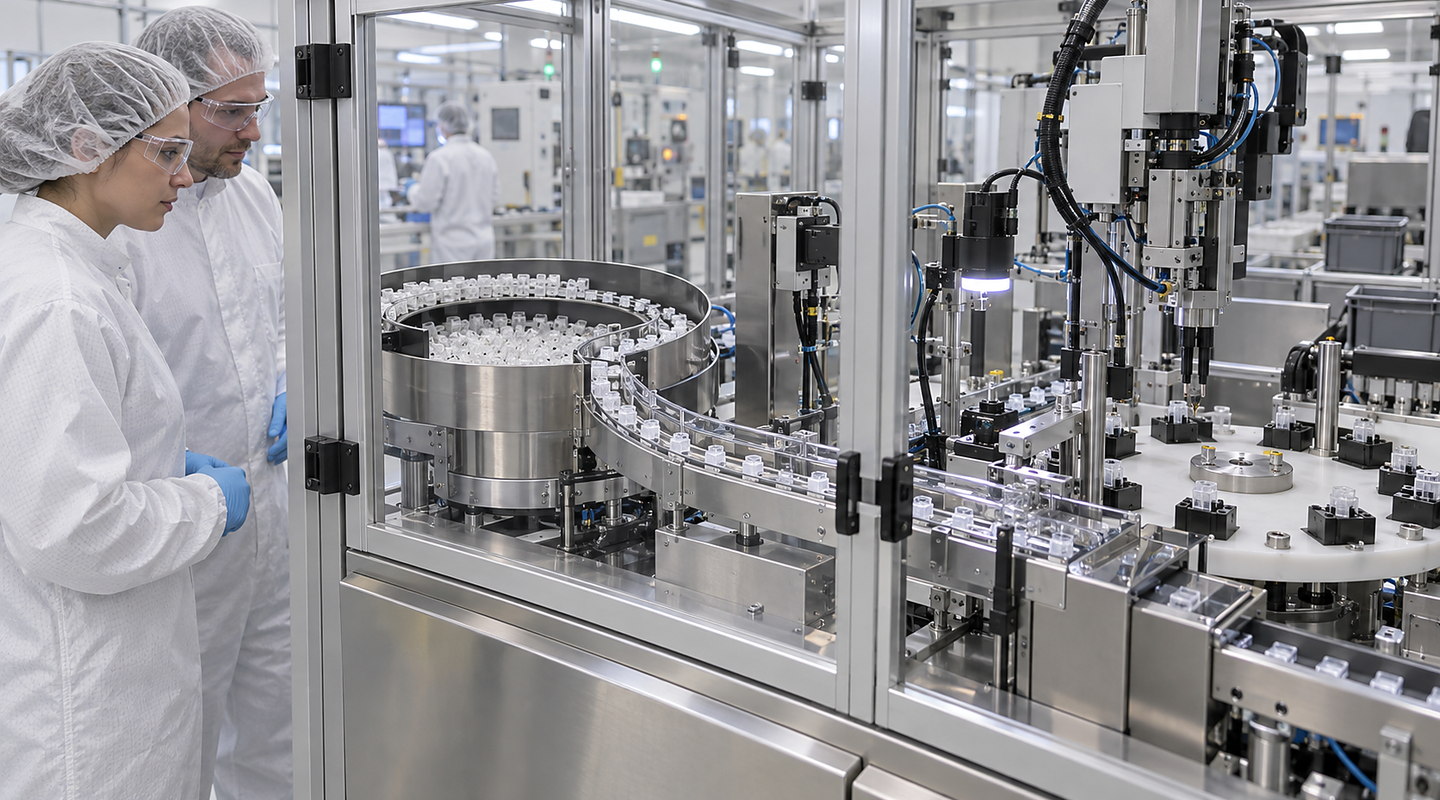
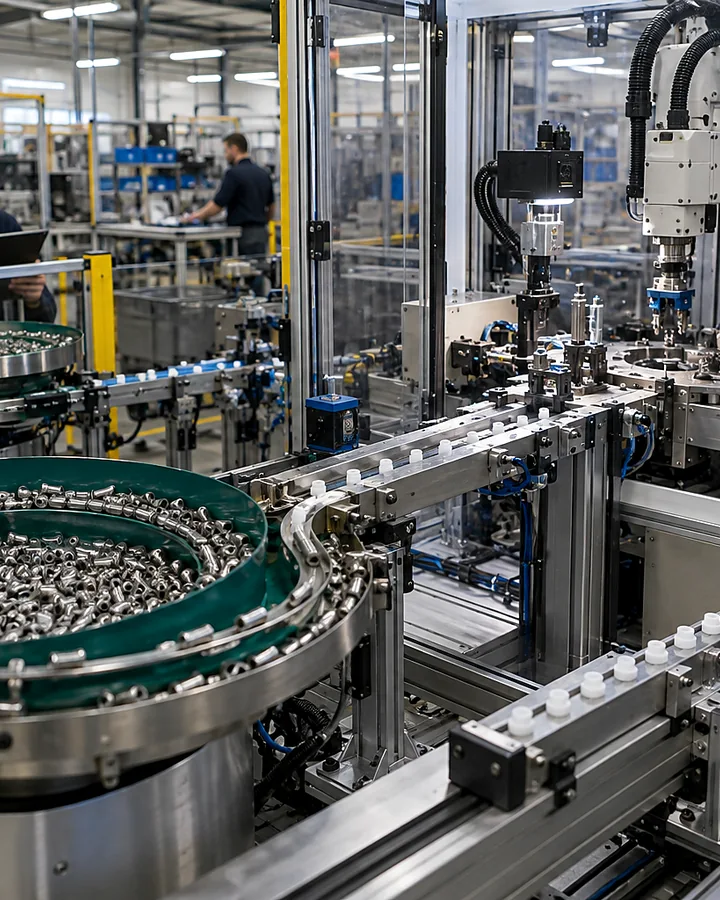
Component Geometry and Variation for Syringe-Component Feeding & Orientation: Component sample trial
How should component geometry and variation for syringe-component feeding & orientation be investigated before specifying syringe part feeders?
In brief
Use current drawings and identified normal, marginal and supplier-variant components to define the range a feeder trial must cover. Record the required assembly orientation, permitted contact areas and downstream handover. Geometry alone does not establish how a component separates or transfers; review surface, fragility and entanglement as well.
For bulk presentation using syringe-component feeding and orientation, describe the realistic range and how changes in component geometry and variation for syringe-component feeding & orientation affect the result you need.
On the production floor
Turn your production information into clearer decisions — Syringe Part Feeders
Plan syringe part feeders around real component variation, bulk condition, orientation, usable delivery rate and the downstream interface. Discuss representative part trials with Sorting Solutions. Use this guide to resolve component geometry and variation for syringe-component feeding & orientation before it limits the final system.
Component Geometry and Variation for Syringe-Component Feeding & Orientation: condition, range and effect on your process
Current condition
Describe how you observe or measure component geometry and variation for syringe-component feeding & orientation in your operation, including sample condition and any measuring limits. For a project focused on syringe-component feeding and orientation, also record the production state in which each observation was made.
Realistic range
For Syringe Part Feeders, include normal production conditions, credible extremes, product or part variants and changes over time.
Effect on the system
Show which settings, safeguards, maintenance tasks, decisions or required outcomes are affected by changes in component geometry and variation for syringe-component feeding & orientation.
Before you contact us
Five questions about component geometry and variation for syringe-component feeding & orientation for your application
Who can confirm this information?Identify the person responsible for component geometry and variation for syringe-component feeding & orientation in production, quality, engineering or operations.
How representative is the sample?Include age, supplier, batch, environment and upstream process state where they affect syringe part feeders.
What is the difficult condition?Include the agreed marginal and supplier-variant components, difficult bulk presentation and uncertain handling or entanglement cases; identify the scope each sample is intended to demonstrate.
How will you judge the result?Agree the method, repetitions, acceptable range, result record and the response if the observed result falls outside the agreed range.
What else must be coordinated?Your final syringe part feeders scope must also account for escapement and downstream pick interface, jam, damage and recovery acceptance checks, current regulations and the conditions at your site.
Connected details
Review component geometry and variation for syringe-component feeding & orientation as part of the complete system
Question 1
Component Geometry and Variation for Syringe-Component Feeding & Orientation
Identify the component, drawing revision, supplier variant and sample group. Separate stated drawing limits from the variation represented by the supplied parts, and record any important range that is not yet covered.
Question 2
Surface, Fragility and Entanglement Behaviour
Mark critical surfaces and permitted contact areas on the drawing or sample record. Carry the manufacturer-defined handling requirements into the trial; shape or appearance alone does not establish acceptable contact or cleanliness.
Question 3
Bulk Condition and Replenishment Method
Describe how components arrive in bulk and how replenishment changes that condition. Trial the agreed normal and difficult presentation with the identified sample groups, recording separation and intervention observations.
Question 4
Required Orientation and Delivery Rate
Show the required final assembly orientation and the usable delivery needed at the next process. Record whether each trial variant reaches that handover as required, rather than counting feeder discharge alone.
Question 5
Escapement and Downstream Pick Interface
Provide the transfer datums, pick envelope and downstream ready conditions. Record where variant geometry changes the physical handover or leaves an interface assumption still to be checked.
Question 6
Jam, Damage and Recovery Acceptance Checks
Retain the trial method, sample identities, setup and results for jams, damage, mixed variants and controlled recovery. Limit conclusions to the component range and operating conditions actually assessed.